
- Home /
- Solutions /
- Pneumatic Conveying Solutions /
- Master-Slave Automation & Control
- SaveEco Flow · Master-Slave Automation & Control
Master-Slave Automation & Control
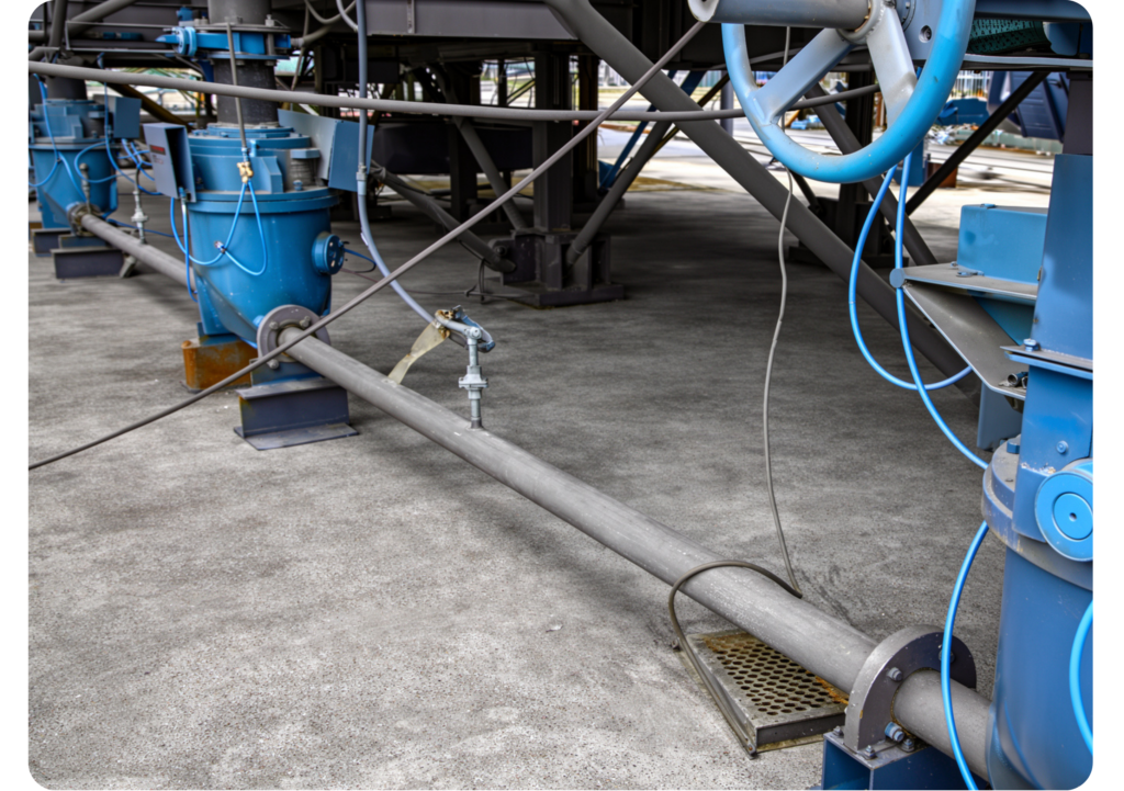
PLC-based sequential control for Series (Master-Slave) vessel conveying — managing multiple slave pressure vessels collecting dry powder from ESP hoppers and bag filter hoppers, and coordinating discharge into a master conveying vessel for fully unattended automatic operation.
- Customers
Trusted by India's Industrial Leaders


- 1.1 Vessel Sizing & Cycle Time
Not a catalogue product — engineered to the specific plant layout, hopper count, and transfer distance.
A Master-Slave Series Vessel Conveying system is sized and engineered to the specific plant layout, hopper count, dust load, and transfer distance of each installation. The following parameters govern system design and are established during the pre-engineering phase.
- 1.1 Key Material Properties for Dense Phase System Design
Each slave vessel volume is selected to match the fill rate of the hopper above it and the required throughput contribution from that collection point. The vessel cycle must complete within a time budget that allows the PLC to sequence all slave vessels without creating a gap in pipeline flow.
| Design Parameter | Basis & Typical Range |
|---|---|
| Slave vessel volume | 0.04 – 1 m³ — determined by hopper fill rate (kg/hr) and required cycle time |
| Vessel cycle time | Typically 3 – 8 minutes per full cycle — fill → pressurise → discharge → vent → reset |
| Slave vessel count | One per hopper outlet — up to 20+ per master system in large ESP installations |
| Simultaneous discharge | PLC-enforced maximum — typically 1 vessel discharging at any time; increases with pipeline capacity |
| Master vessel volume | Sized to buffer discharge from all slave vessels without pipeline starvation or overload |
| Operating pressure | 3.5 bar gauge — consistent across all slave vessels in the series |
| Conveying distance | 0.1 – 0.5 km from slave vessel outlet to master vessel or receiving silo |
| Total throughput | 1 – 50 TPH — aggregate of all slave vessels in sequence |
- 1.2 Material Properties Relevant to Slave Vessel Design
Design parameters are established through material characterisation testing — particle size analysis, bulk density, moisture content, and angle of repose — prior to vessel and pipeline sizing.
| Property | Relevance | Design Implication |
|---|---|---|
| Bulk density | Mass per vessel charge and cycle throughput | Low bulk density (fly ash 700–900 kg/m³) requires larger vessel volume for equivalent mass per cycle |
| Particle size (d₅₀) | Conveying velocity and separator sizing | Fine fractions (<30 µm, typical fly ash) require bag filter at receiving silo |
| Moisture content | Caking risk in vessel and pipeline | Compressed air dewpoint ≤ −20°C PDP for hygroscopic materials — cement dust, limestone |
| Abrasiveness (Mohs) | Vessel discharge valve and pipeline life | Fly ash (Mohs 5–6): hardened valve seats and ceramic-lined bends |
| Explosibility (Kst) | ATEX equipment class | Coal dust: ATEX Zone 20/21 — vessels, valves, and PLC panel earthed; explosion relief on master vessel |
| Flowability | Reliability of gravity fill | Poor-flowing materials may require aeration pads on hopper cone or vibration |
- 2. Control Cycle — How the System Operates
Five phases. One PLC. Near-continuous material flow from batch-operating vessels.
Each slave vessel operates through a repeating five-phase cycle managed by the PLC. The control system staggers these cycles across all slave vessels so that the conveying pipeline receives a near-continuous feed of material from successive vessels in rotation — maximising pipeline utilisation without overloading the shared conveying pipe.
01
Fill
Fill — Gravity Feed from Hopper
The slave vessel inlet valve opens and the vessel fills by gravity from the ESP or bag filter hopper above. A high-level sensor or timed fill cycle signals the PLC when the vessel is charged. The inlet valve closes to seal the vessel before pressurisation begins — preventing any air from entering the hopper during the pressure phase.
02
Pressurise
Pressurise — Compressed Air Charge
Compressed air is admitted to the vessel. The PLC monitors vessel pressure via the dedicated pressure transmitter and confirms the vessel has reached the conveying pressure setpoint (up to 3.5 bar) before enabling the discharge valve to open. This pressure confirmation interlock is a critical safety step — it prevents the discharge valve from opening against a partially pressurised vessel.
03
Discharge
Discharge — Material Transfer to Pipeline
The discharge valve opens and compressed air drives material from the slave vessel into the shared conveying pipeline. The PLC monitors discharge duration and pipeline pressure profile. When the vessel is confirmed empty — by timed discharge cycle or by pipeline pressure drop indicating flow completion — the discharge valve closes and the vent phase begins.
04
Vent
Vent & Depressurise
The vessel is depressurised through a controlled vent valve to atmosphere before the inlet valve can reopen for the next fill cycle. The PLC holds the vessel in vent state until vessel pressure is confirmed at atmospheric — preventing any unsafe opening of the inlet valve against residual vessel pressure, which would cause a pressure surge back into the hopper.
05
Rotation
Sequential Rotation — All Slave Vessels
While one vessel discharges, adjacent vessels are in fill or pressurise phase. The PLC staggers cycle start times across all slave vessels to maintain near-continuous pipeline flow. The maximum number of simultaneously discharging vessels is enforced by the PLC at all times — pipeline overload is not a function of the number of vessels but of the sequencing logic.
Why sequencing matters: In a 10-vessel slave installation, uncoordinated simultaneous discharge would flood the shared conveying pipeline with 10× the designed mass flow rate — causing immediate blockage. The PLC sequencing logic is what converts ten independently batch-cycling pressure vessels into a single, coordinated, near-continuous conveying system. This is the core engineering value of the Master-Slave control architecture.
- 3. Automation & Control System Architecture
Built for fully unattended automatic operation across all slave vessels simultaneously.
The Master-Slave control system is built on a PLC platform with hardwired safety interlocks, dedicated field instrumentation at each slave vessel, and a centralised operator interface. The control architecture is designed for fully unattended automatic operation.
- 3.1 PLC Control Platform
A Programmable Logic Controller (PLC) programmed with sequencing logic, timing parameters, pressure setpoints, and interlock conditions for all slave vessels is the central control element. The PLC communicates with all field devices — pressure transmitters, level sensors, valve position feedback switches — via hardwired I/O. All vessel cycle states, alarm detection, interlock enforcement, and operator commands are managed within a single PLC execution environment.
Platform selection: SaveEco selects the PLC platform based on project requirements, client preference, and plant instrumentation standards. Industry-standard PLC platforms are used — the specific make and model is confirmed during engineering. The control logic, sequencing program, and HMI are developed and configured by SaveEco’s automation engineering team as part of the system supply scope.
- 3.2 Field Instrumentation Per Slave Vessel
Each slave vessel is equipped with dedicated instrumentation required for the PLC to manage its cycle fully automatically — no manual intervention at the vessel location is required during normal operation.
Pressure Transmitter
Range: 0 – 5 bar gauge; accuracy 0.5%; 4–20 mA output; process connection to vessel
Inlet Valve (Actuated)
Pneumatically actuated; open/close position limit switches; pressure rating to match vessel design pressure
Discharge Valve (Actuated)
Pneumatically actuated; open/close position switches; pressure rating 3.5 bar g; abrasion-resistant seat material
Vent Valve
Normally closed; pneumatically actuated; vent discharge routed to safe location or back to filter receiver
Level Sensor / Fill Timer
Capacitance or vibrating fork level switch at vessel high level; or timed fill cycle as alternative
Pipeline Pressure Transmitter
Range 0 – 5 bar gauge; 4–20 mA output; installed at pipeline common header
- 3.3 Operator Interface — HMI & Alarm Management
Each slave vessel is equipped with dedicated instrumentation required for the PLC to manage its cycle fully automatically — no manual intervention at the vessel location is required during normal operation.
HMI / SCADA Screen
Graphical display showing real-time state of each slave vessel (Fill / Pressurise / Discharge / Vent / Fault), shared pipeline pressure, and receiving silo level. Cycle counter per vessel for maintenance scheduling.
Alarm Management
Hardwired and software alarms for: vessel overpressure; inlet / discharge / vent valve fault (position not confirmed within timeout); level sensor failure; pipeline blockage indication (sustained high pipeline pressure); silo high-level. Alarms logged with timestamp and vessel identity for maintenance analysis.
Manual Override
Individual vessel manual control mode for commissioning, maintenance bypass, and fault recovery. Interlocks remain active in manual mode to prevent unsafe operation — discharge valve cannot open unless vessel pressure is at setpoint.
Sequence Adjustment
Operator-adjustable parameters for fill duration, pressurise ramp time, discharge cycle time, and inter-vessel stagger interval. Parameters are tuned to actual material properties and hopper fill rates during commissioning and can be adjusted by the plant engineer without reprogramming.
Remote Start / Stop
System start/stop commands available via HMI and via hardwired contact input from plant DCS or control room. System running status, active alarm summary, and vessel cycle count transmitted back to plant DCS.
- 3.4 DCS / SCADA Integration
The PLC-based master-slave control panel provides a standard communication interface for integration with the plant Distributed Control System (DCS) or SCADA. The following signals are exchanged across the plant fieldbus or hardwired signal interface.
Lorem ipsum dolor sit amet, consectetur adipiscing elit. Ut elit tellus, luctus nec ullamcorper mattis, pulvinar dapibus leo.
Communication protocol (Profibus DP, Profinet, Modbus TCP, hardwired signals, or OPC UA) is confirmed during instrumentation engineering based on plant DCS platform and existing fieldbus infrastructure.
- 4. System Components & Engineering Specifications
Mechanical vessels, shared pipeline, instrumentation, and central PLC — one integrated system.
The Master-Slave Series Vessel Conveying system integrates mechanical vessels, shared conveying pipeline, field instrumentation, and the central PLC control panel. All elements must be correctly specified and matched to material properties, vessel count, throughput, and distance requirements.
| Component | Engineering Function | Key Specification Parameters |
|---|---|---|
| Slave Pressure Vessel | Receives material by gravity from hopper; seals; pressurises; discharges into shared conveying pipeline under PLC control | Volume (m³); design pressure (min. 3.5 bar g); cone angle; discharge valve type; aeration provision for cohesive materials |
| Master Vessel | Receives consolidated discharge from all slave vessels; accumulates material before onward long-distance conveying if required | Volume (m³) — sized to buffer all slave vessel discharge; design pressure 3.5 bar g |
| Shared Conveying Pipeline | Single pipeline receiving sequential discharge from all slave vessels — transfers material at dense phase conditions to master vessel or receiving silo | Bore (mm) — sized for maximum single-vessel discharge rate; wall thickness; hardened bends at direction changes |
| Vessel Inlet Valve | Opens for gravity fill from hopper; closes and seals vessel against conveying pressure before pressurisation | Pneumatic actuation; open/close position switches; pressure rating ≥ vessel design pressure; material-compatible seat |
| Vessel Discharge Valve | Opens when vessel is at conveying pressure setpoint; discharges into shared pipeline; closes on cycle completion | Pressure rating 3.5 bar g; pneumatic actuation; position switches; abrasion-resistant seat material |
| Vent Valve | Controlled vessel depressurisation to atmosphere between discharge and refill — prevents unsafe inlet valve opening against residual pressure | Normally closed; pneumatic actuation; vent line routed to safe discharge point |
| Pressure Transmitter | Monitors vessel pressure at all cycle phases — the primary PLC feedback instrument for sequencing logic and safety interlock | Range 0–5 bar g; accuracy 0.5%; 4–20 mA output; process connection to vessel |
| Screw Compressor / Air Supply | Delivers compressed air at 3.5 bar to all slave vessels — single shared compressed air header serves all vessel pressurisation and conveying air demand | FAD (m³/min) — sized for maximum simultaneous pressurisation demand; delivery pressure 3.5 bar; dewpoint to material specification |
| PLC Control Panel | Central operational hub — houses PLC, I/O modules, HMI, power supply, communication interfaces; manages all vessel cycle sequencing and plant integration | PLC platform; I/O count; HMI screen size; panel IP rating; communication interface to plant DCS |
| Receiving Silo / Filter Receiver | Terminal point — stores collected material; vent filter retains dust during vessel discharge air venting; level monitoring provides silo high signal to PLC | Capacity (m³); vent filter type; filter cloth area (m²); differential pressure monitoring |
- 5. Industries & Process Applications
Wherever multiple individual hoppers must be collected into one conveying pipeline.
The Series (Master-Slave) vessel configuration is the standard approach wherever multiple individual dust-generating sources — each with its own hopper — must be collected and consolidated into a single conveying pipeline. The architecture eliminates mechanical multi-hopper conveyors, replacing them with a fully enclosed pneumatic system with no rotating in-pipeline parts.
| Industry | Process Context | System Configuration & Key Requirement |
|---|---|---|
| Thermal Power Plants — ESP | Multiple ESP fields (3–6 fields, 4–8 hopper rows each) collect fly ash. Hopper count in a 500 MW plant can exceed 60–80. Continuous evacuation required to prevent ESP blinding. | Slave vessels beneath each hopper row; master vessel for onward silo transfer; hardened discharge valves and bends for fly ash abrasion; 3.5 bar operating pressure |
| Thermal Power Plants — Bag Filter | Fabric filter bag houses — multiple filter compartments each with individual hopper outlets requiring continuous dust removal. | Slave vessels beneath each bag filter compartment; PLC-controlled to prevent simultaneous discharge overloading shared pipeline |
| Cement Plants — Preheater & Raw Mill | Kiln preheater tower and raw mill systems have multiple dedusting bag filter units — each with hopper outlets containing raw meal or cement dust. Continuous removal required to maintain filter efficiency. | Slave vessels at each bag filter hopper; compressed air dewpoint ≤ −20°C PDP for cement and raw meal; abrasion-resistant bends |
| Integrated Steel Plants | Blast furnace gas cleaning, BOF converter dedusting, and sinter plant dedusting generate fine metallic and process dust at multiple hopper collection points across large plant areas. | Large slave vessel count (10–20+) across extended plant footprint; ATEX provisions for BOF dust; hardened system for metallic abrasive dusts |
| Alumina Refineries | Rotary kilns and calciners fitted with multiple bag filter units for product recovery. Calcined alumina (Mohs 9) requires careful system design. | Slave vessels at each calciner bag filter; ceramic-lined bends at all direction changes; hardened discharge valves for Mohs 9 material |
| Chemical & Mineral Processing | Multi-stage process equipment (reactors, dryers, cyclones) with individual hopper outlets containing fine chemical or mineral powders. | System design varies by material — vacuum conveying may be required for fine chemical applications; ATEX for explosive dust classifications |
- 6. Engineering Advantages
Inherent advantages of the correctly designed and programmed Master-Slave control architecture.
The following advantages are inherent to the correctly designed and programmed Master-Slave Series Vessel Conveying system and apply to installations with suitable materials and plant layouts.
Single Point of Control for Multiple Sources
All slave vessels — regardless of how many hoppers are served — are managed from one PLC panel. Operators monitor the entire multi-source collection system from one location without visiting individual vessels or operating local controls at each collection point across the plant.
Near-Continuous Throughput from Batch Vessels
Sequential staggering of vessel cycles by the PLC creates near-continuous material flow in the shared conveying pipeline from a set of batch-operating pressure vessels — maximising pipeline utilisation and minimising the conveying dead time inherent in single-vessel batch operation.
Eliminates Mechanical Multi-Hopper Conveyors
Screw conveyors, drag chains, and belt feeders traditionally used to collect material from multiple hoppers have rotating in-pipeline parts requiring regular maintenance and creating open-transfer dust generation points. The Master-Slave architecture replaces these with a fully enclosed pneumatic system with no rotating in-pipeline parts.
Prevents Pipeline Overload & Blockage
The PLC enforces a maximum number of simultaneously discharging vessels at all times. This prevents the shared conveying pipeline from receiving more material than it can carry at dense phase conditions — the primary cause of pipeline blockage in manually operated multi-vessel systems.
Automated Fault Detection & Safe-State Response
Pressure transmitter readings, valve position feedback, and cycle timing are continuously monitored by the PLC. Deviations — overpressure, valve stuck open or closed, discharge not completing within expected time — are detected immediately and the affected vessel is placed into a safe state with an operator alarm generated.
Flexible Vessel Count & Expansion
Additional slave vessels can be added to the control system by extending the PLC I/O and adding vessel sequences to the control program — without redesigning the master conveying pipeline or the central control panel, provided pipeline capacity is adequate.
Reduced Manual Intervention Across Large Plant Areas
Fully automatic sequential operation eliminates the need for operators to manually pressurise, discharge, and vent individual vessels at each hopper location — particularly critical in installations where slave vessels are distributed across several floors of a large ESP gallery or across different buildings in an integrated steel plant.
- 7. System Integration
An integral part of the Series Vessel Conveying installation — not a separate add-on.
The master-slave automation and control system is designed, supplied, and commissioned together with the mechanical system as a single turnkey scope. The integration points below show how the automation system connects to each element of the complete installation.
01
ESP / Bag Filter Hoppers
Dust generated at multiple process points accumulates in individual hoppers above each slave vessel — the material collection points that drive the fill phase of each vessel cycle.
Hopper level monitoring (optional high-level alarm) wired to PLC; slave vessel fill cycle triggered by hopper level or timed schedule
02
Slave Vessels & Instrumentation
Each slave vessel has its dedicated pressure transmitter, actuated inlet and discharge valves, vent valve, and level detection — all wired to the central PLC.
All field devices hardwired to PLC I/O; valve position feedback is the primary cycle integrity check at each phase transition
03
Shared Conveying Pipeline
Single pipeline receives sequential discharge from all slave vessels; conveys material at dense phase conditions (3.5 bar, 0.1–0.5 km) to master vessel or receiving silo.
Pipeline pressure transmitter at common header monitors blockage and overpressure; signal hardwired to PLC
04
Master Vessel or Receiving Silo
Collected material arrives at master vessel (for onward conveying) or directly at storage silo; level monitoring provides system back-pressure protection.
Receiving silo high-level signal wired to PLC — pauses all slave vessel discharge cycles when silo is full
05
Compressed Air System
Single shared compressed air header at 3.5 bar supplies all vessel pressurisation and conveying air — sized for maximum simultaneous demand.
Supply pressure monitoring; low-pressure alarm to PLC — prevents vessel pressurisation from being attempted below minimum conveying pressure
06
Plant DCS / SCADA
Plant-wide process control and monitoring system — receives system status, alarms, and cycle data from PLC; issues remote start/stop commands.
Standard fieldbus or hardwired interface; protocol confirmed during engineering (Profibus, Profinet, Modbus TCP, or OPC UA)
Turnkey engineering scope: SaveEco engineers the complete Series Vessel Conveying system — mechanical vessels, shared pipeline, field instrumentation, PLC programming, HMI configuration, loop testing, commissioning, and plant DCS integration — as a single turnkey scope with one point of accountability for system performance.
- Frequently Asked Question
Common questions about Master-Slave automation and control.
Engineer Your Master-Slave Conveying System with SaveEco Energy
Whether you are handling fly ash from a multi-field ESP, dust from multiple bag filter outlets, or fine powder from distributed process hoppers — SaveEco’s engineering team designs the Series Vessel Conveying system and its master-slave automation to match your specific source layout, hopper count, transfer distance, and material.
What to expect: Process review · Vessel & pipeline sizing · Instrumentation specification · PLC architecture · DCS/SCADA integration · Commissioning support