
- Home /
- Solutions /
- Pneumatic Conveying Solutions /
- Lean PhaseConveying Systems
- SaveEco Flow · Lean Phase Conveying
Lean Phase Conveying Systems
High-velocity, flexible bulk powder transfer for short-to-medium distance in-plant distribution. Engineered for free-flowing dry powders, process feeding, and dust-free enclosed conveying.
- Customers
Trusted by India's Industrial Leaders


- Section 01
Material Properties & Conveyability
Lean phase conveying is suited to a specific category of bulk powder — free-flowing, relatively light, and non-abrasive to moderately abrasive. Correct system selection depends on understanding how material properties interact with the high-velocity suspension flow regime that defines lean phase conveying.
- Critical Design Constraint
The Saltation Velocity
In lean phase conveying, every particle must remain in full air suspension throughout the entire pipeline length. The minimum air velocity at which a given particle will remain suspended — and below which it will settle and cause blockage — is the saltation velocity.
For most fine industrial dry powders (d₅₀ < 150 µm), saltation velocity typically falls in the range of 10–20 m/s. Operating velocity is set comfortably above this to provide an adequate safety margin.
- Key Material Properties for System Design
Particle Size (d₅₀)
Saltation velocity & air velocity
Finer particles (< 100 µm) have lower saltation velocity; coarser particles require higher air velocity and larger pipeline bore.
Bulk Density
Air-to-material ratio & blower sizing
Low bulk density materials (< 500 kg/m³) are well suited to lean phase; high bulk density sharply increases air volume demand.
Particle Density
Saltation velocity calculation
Heavier particles require higher conveying velocity to remain suspended — increases blower energy requirement.
Abrasiveness (Mohs)
Pipeline & bend wear life
Not recommended for materials with Mohs > 5 over distances > 30–50 m — pipeline and bend wear becomes excessive at lean phase velocities.
Flowability / Angle of Repose
Entrainment at feed point
Cohesive materials (angle of repose > 45°) may not entrain reliably without additional agitation at the rotary airlock or pickup point.
Moisture Content
Inter-particle cohesion & wall adhesion
Materials with moisture content > 1–2% typically require pre-drying or are unsuitable for lean phase without specific design provisions.
- Reference Material Data — Lean Phase Suitability
| Material | Typical D50 | Status | Design Note |
|---|---|---|---|
| Cement Powder (OPC/PPC) | 15 – 45 µm | Suitable | Short in-plant runs up to 100 m. Compressed air dewpoint ≤ -20°C PDP mandatory. Dense phase preferred beyond 100 m to control abrasion. |
| Fly Ash — Class F | 10 – 30 µm | Suitable | Short transfers from local bag filter to nearby hopper. Dense phase is the standard for ESP-to-silo transfers exceeding 100 m. |
| Limestone Powder | 20 – 75 µm | Suitable | Moderate abrasion — pipeline bore and bend specification required. Dense phase recommended beyond 50–80 m. |
| Gypsum Powder | 30 – 100 µm | Suitable | Low abrasion; hygroscopic — compressed air drying required. Good entrainment at lean phase velocities. |
| Fine Coal Dust | 50 – 300 µm | Suitable* | Short injection/dosing runs only. ATEX Zone 20/21 provisions mandatory. Earthed pipework and explosion relief required. |
| Chemical Powders (Light) | 5 – 100 µm | Suitable | Suitable where bulk density < 600 kg/m³ and abrasiveness is low. Vacuum mode preferred for sensitive powders. |
| Metal Oxide Powders | 0.1 – 20 µm | Suitable | Short sealed runs. Vacuum mode preferred — prevents material escape. HEPA-grade filtration required. |
| Calcined Alumina | 80 – 150 µm | Not Recommended | Mohs 9 abrasiveness causes rapid erosion. Dense phase conveying is mandatory. |
| Pulverised Coal (PCI) | 50 – 200 µm | Not Recommended | ATEX complexity + high abrasion makes lean phase unsuitable. Dense phase injection preferred. |
- Section 02
System Configurations
SaveEco, in partnership with STAG AG Switzerland, offers three lean phase conveying configurations — each addressing a distinct plant requirement. Configuration selection is driven by drive mode, required throughput, process feeding precision, and material properties.
Configuration 2.1
Pressure Conveying
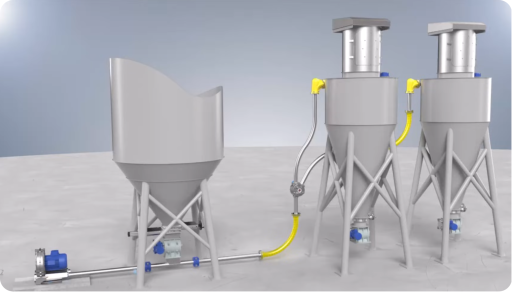
A roots blower or low-pressure screw compressor supplies air at up to 1.2 bar gauge. Material is metered into the pressurised air stream through a rotary airlock valve and carried at high velocity to a bag filter or cyclone receiver. Suited to single-source to single or multi-destination in-plant powder transfer.
| Capacity | 0.5 – 20 T per cycle |
| Pressure | Up to 1.2 bar gauge |
| Distance | Up to 100 m |
| Drive | Roots blower or low-pressure screw compressor |
| Feed Device | Rotary airlock valve — seals pressurised pipeline from atmospheric hopper |
Silo → Process Hopper → Cement → Mill Feed Bin — Multi-destination via diverter valves
Configuration 2.2
Vacuum Conveying
A vacuum pump or exhaustor draws air through the pipeline, creating suction that entrains material from the pickup point to the central receiver. Because the pipeline operates below atmospheric pressure, any imperfect seal draws ambient air inward — not material outward. The preferred mode for hygroscopic, fine, or health-classified powders.
| Capacity | 0.5 – 20 T per cycle |
| Pressure | Up to 1.2 bar (negative gauge) |
| Distance | Up to 100 m |
| Drive | Vacuum pump or exhaustor |
| Feed Device | Open pickup nozzle or inlet valve — material entrained directly by suction |
Bag unloading · Jumbo bag stations · Centralised vacuum housekeeping · Health-classified powders
Configuration 2.3
Injection / Dosing System
Where the downstream process requires a controlled, metered mass-flow feed rate rather than bulk batch transfer, SaveEco supplies injection and dosing systems using rotary dosing valves and air injector nozzles. These deliver a stable, adjustable mass flow of dry powder directly into a process vessel, reactor, or kiln.
| Application | Precision mass-flow process feeding — continuous and adjustable |
| Feed Device | Rotary dosing valve or screw dosing feeder — mass-flow controlled |
| Air Nozzle | Geometry engineered to specific material bulk density and required mass flow rate |
| Material | Dry powders requiring precise, stable, pulsation-free feed rate |
Blast furnace injection · Cement kiln firing · Chemical reactor dosing · De-sulphurisation reagent
The air injector nozzle controls the precise point and angle at which compressed air entrains material into the conveying line. Nozzle geometry is engineered to the specific material bulk density and required mass flow rate, ensuring stable entrainment without pulsation or flow instability. This precision is the critical differentiator between an injection system and a standard lean phase pressure conveying line.
- Section 03
System Components & Engineering Specifications
A complete lean phase conveying system integrates air supply, material feed, pipeline, separation, and control elements. Each component must be correctly specified for the material’s flow properties, required conveying velocity, throughput, and target service life.
| Component | Engineering Function | Key Specification Parameters |
|---|---|---|
Air Mover — Blower or Compressor | Supplies pressurised air at required pressure and flow rate to maintain conveying velocity throughout the pipeline | Type (roots blower / screw compressor / vacuum pump / exhaustor); delivery pressure (bar g); free air delivery (m³/min); motor power (kW) |
Rotary Airlock Valve | Meters bulk material into pressurised conveying line while sealing pressure differential | Rotor diameter; pocket volume; RPM; differential pressure rating; rotor tip clearance; material of construction |
Conveying Pipeline | Enclosed transfer path carrying air-material suspension from feed point to receiver | Bore (mm); wall thickness; material grade; bend radius (min 6× bore); expansion provisions |
Diverter Valves | Routes material to one of multiple receiving points for multi-destination delivery | Number of outlets; bore; pressure rating; actuator type; position feedback; switching cycle time |
Receiver — Cyclone / Bag Filter | Separates conveyed material from carrier air; retains dust while venting clean air | Separator type; inlet velocity; collection efficiency; filter cloth area; air-to-cloth ratio; DP monitoring |
Rotary Dosing Valve / Screw Feeder | Controls mass flow rate of material entering conveying line for process feed applications | Mass flow range (kg/h); feed accuracy; drive type; integration with control system |
PLC Control System | Manages conveying cycle, monitors pressures and levels, handles alarms and interlocks, interfaces with DCS/SCADA | PLC platform; I/O count; HMI; communication protocol (Profibus/Profinet/Modbus); integration standard |
- Section 04
Industries & Process Applications
Lean phase conveying serves as the in-plant distribution and process feeding layer — handling short-to-medium distance powder transfer within a facility, from silo outlet to process equipment.
| Industry | Process Application | Lean Phase System Requirement |
|---|---|---|
Cement Manufacturing | Process Application
Cement powder from mill discharge to packing plant or dispatch silo; raw meal from feed hopper; gypsum addition to mill inlet. Typical runs < 80 m. | System Requirement
Pressure conveying with rotary airlock valve. Dewpoint ≤ -20°C PDP. Hardened bends at direction changes. Dense phase beyond 80–100 m. |
Thermal Power Plants | Process Application
Fly ash transfer from bag filter to hopper. Vacuum housekeeping for ESP floors and ash handling areas. | System Requirement
Vacuum conveying with inlet stations. Pressure conveying for short ash transfer. |
Integrated Steel Plants | Process Application
Coal dust injection into furnace; lime injection; reagent dosing systems. | System Requirement
Injection system with dosing valve and injector nozzle. ATEX Zone 20/21 compliance. Explosion relief required. |
Chemical Processing | Process Application
Powder transfer between process stages. Vacuum conveying for sensitive powders. | System Requirement
Vacuum conveying preferred. HEPA filtration. Stainless steel pipeline for product contact. |
Mineral Processing | Process Application
Limestone and gypsum transfer to dosing systems. Distribution via diverter valves. | System Requirement
Pressure conveying with diverter valves. Moderate abrasion handling. |
Bag / Jumbo Bag Unloading | Process Application
Discharge of bags into vacuum pickup system without open tipping. | System Requirement
Vacuum pickup with sealed bag spout. Dust-free discharge into pipeline. |
- Section 05
Lean Phase vs. Dense Phase — Engineering Selection Guide
SaveEco engineers both lean phase and dense phase systems and selects the appropriate conveying mode based on material characterisation, throughput, distance, and plant layout. Many installations combine both: long-distance inter-building transfer in dense phase, with short in-plant distribution in lean phase.
| Parameter |
Lean Phase Dilute phase · High velocity |
Dense Phase Plug / Slug flow · Low velocity |
|---|---|---|
| Conveying Velocity | 18–28 m/s — particles fully suspended | 1–6 m/s — plug/slug movement |
| Operating Pressure | Up to 1.2 bar (positive / vacuum) | Up to 3.5 bar gauge |
| Solids Loading Ratio | Low — higher air volume required | High — lower air per material |
| Transfer Distance | Up to 100 m | Up to 1.6 km |
| Throughput Range | 0.5 – 20 T per cycle | 1 – 500 TPH |
| Material Suitability | Free-flowing, low to moderate abrasion | Abrasive, cohesive, fine powders |
| Pipeline Wear | Higher — erosion at bends | Lower — reduced erosion |
| Material Degradation | Higher risk | Lower — gentle transport |
| Capital Cost | Lower | Higher |
| Operating Energy | Higher air volume | Lower |
| Precision Dosing | Yes | Not standard |
| Vacuum Operation | Yes | Not applicable |
- Section 06
Multimodal Integration — In-Plant Distribution & Process Feeding Layer
Lean phase conveying functions as the final-stage in-plant distribution and process feeding layer within a complete bulk material logistics chain. SaveEco engineers lean phase systems to interface with upstream unloading infrastructure and with in-plant dense phase long-distance transfer networks, creating a fully enclosed material flow from logistics input to process point.
| Upstream / Parallel System | Equipment Specification | Lean Phase Interface Role |
|---|---|---|
Road Bulker Unloading | 30 / 50 / 70 m³ tankers · 2 bar operating pressure · Unloading time ~30 min · Specific power 1.9 kW/Ton | Interface Role
Lean phase distributes material from silo to process hoppers and mill feed bins after tanker discharge |
Rail Wagon Unloading | 60 m³ wagons · 51 wagons per rake · 2 bar pressure · Unloading ~330 min · Air fluidisation system | Interface Role
Lean phase handles final silo-to-process transfer after wagon discharge into receiving silos |
Ship Transfer — Bulk Carrier | Up to 30,000 m³ capacity · 3.5 bar pressure · Unloading ~30 hrs · Specific power 2.8 kW/Ton | Interface Role
Dense phase fills silos; lean phase manages downstream in-plant distribution |
Tank Container / ISO Tank | 25–30 m³ containers · 2 bar pressure · Unloading ~15 min · 1.4–1.6 kW/Ton | Interface Role
Pneumatic discharge into vessel; lean phase transfers to process hopper or silo |
Dense Phase Long-Distance Transfer | Twin tandem or stand-alone systems up to 1.6 km at 3.5 bar | Interface Role
Dense phase fills silos; lean phase completes final silo-to-process stage |
Bag / Jumbo Bag Unloading | 25 kg bags and 500–1,000 kg jumbo bags with sealed spout connection | Interface Role
Vacuum lean phase picks material directly at bag station — no manual handling or dust |
Centralised Vacuum cleaning system | Fixed vacuum pipeline network with inlet valve stations across plant | Interface Role
Collects fugitive dust from plant areas — returns material to silo or disposal |
- Frequently Asked Question
Technical questions about lean phase conveying & system design
Engineer Your Lean Phase Conveying System with SaveEco Energy
Every lean phase installation is engineered to the site — material properties, throughput, distance, and plant layout. Share your project requirements with our engineering team and receive a technical assessment covering pressure vs. vacuum selection, blower sizing, pipeline design, and integration with your existing plant infrastructure.