
- Home /
- Solutions /
- Pneumatic Conveying Solutions /
- Centralised Vacuum Cleaning Systems
- SaveEco Flow · Pneumatic Vacuum Systems
Centralised Vacuum Cleaning Systems
A permanently installed, plant-wide pneumatic vacuum network that collects fugitive dust, dry powder spillage, and fine particulate from multiple locations across a facility — eliminating manual sweeping, mobile vacuum trolleys, and compressed-air blow-down.
- What Is a Centralised Vacuum Cleaning System?
A fixed, plant-wide vacuum network — one central unit serving the entire facility.
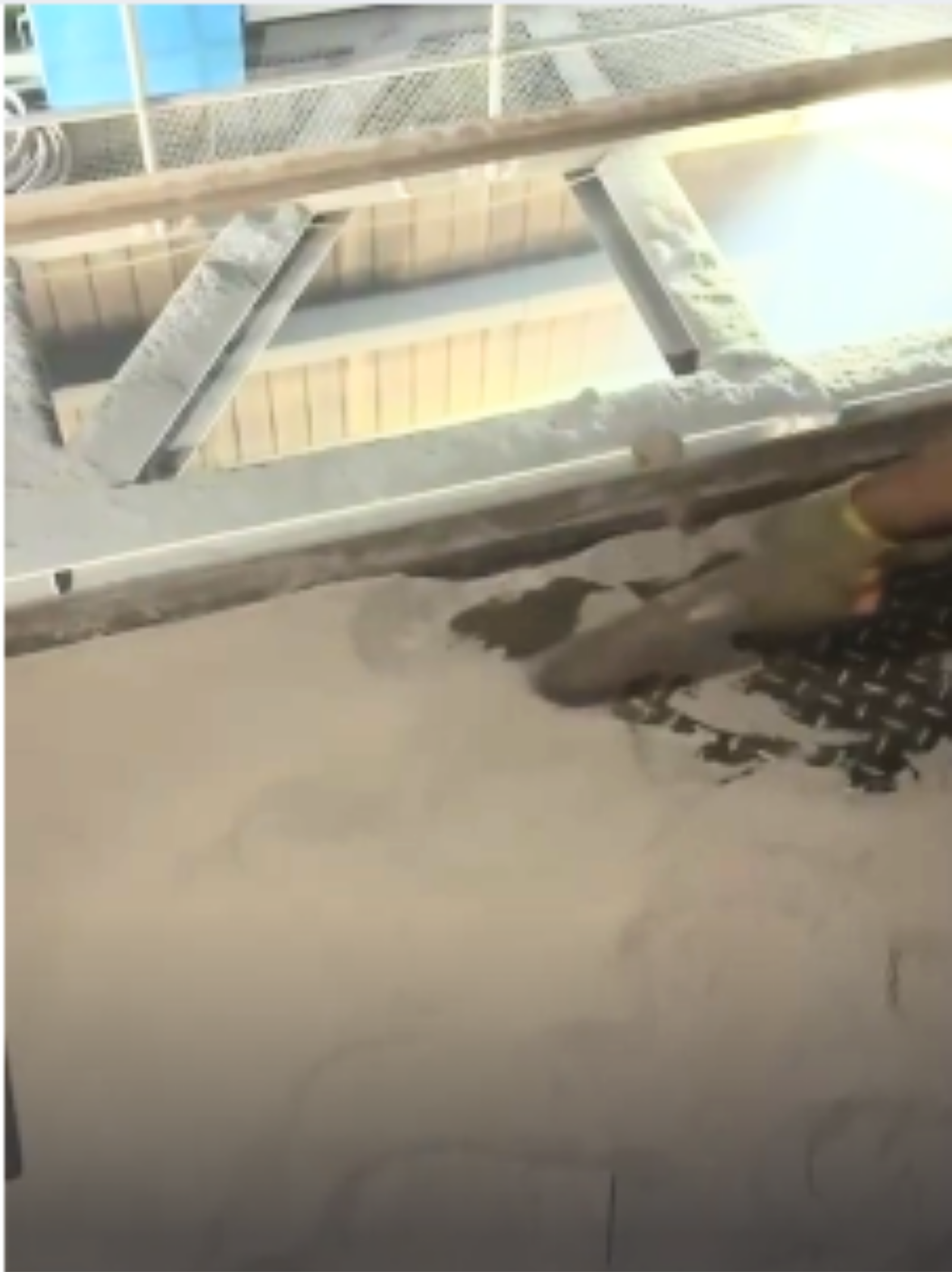
A Centralised Vacuum Cleaning System (CVCS) is a fixed, plant-wide pneumatic vacuum network designed to collect fugitive dust, dry powder spillage, and fine particulate material from multiple points across an industrial facility — and transport that material to a single central collection point via sealed vacuum pipelines.
The system eliminates manual sweeping, mobile vacuum trolleys, and compressed-air blow-down of accumulated dust, replacing these practices with a permanently installed, operator-controlled vacuum infrastructure — or a fully automatic dust recovery network — depending on the application.
A CVCS serves two simultaneous functions: routine housekeeping (cleaning floors, surfaces, and equipment) and fugitive dust recovery (capturing escaped process dust before it becomes an environmental and health risk).
| System Parameter | Specification |
|---|---|
| Drive Method | Negative Pressure / Vacuum |
| Application | Plant Housekeeping & Dust Recovery — Cement, Power, Steel, Chemical |
| Suction Points | Multiple Fixed & Flexible (operator-controlled or automatic) |
| Material Handled | Industrial Dust & Dry Powders |
| Technology Partner | STAG AG, Switzerland — since 1954 |
- Working Principle
Four integrated elements — one enclosed, zero-release collection system.
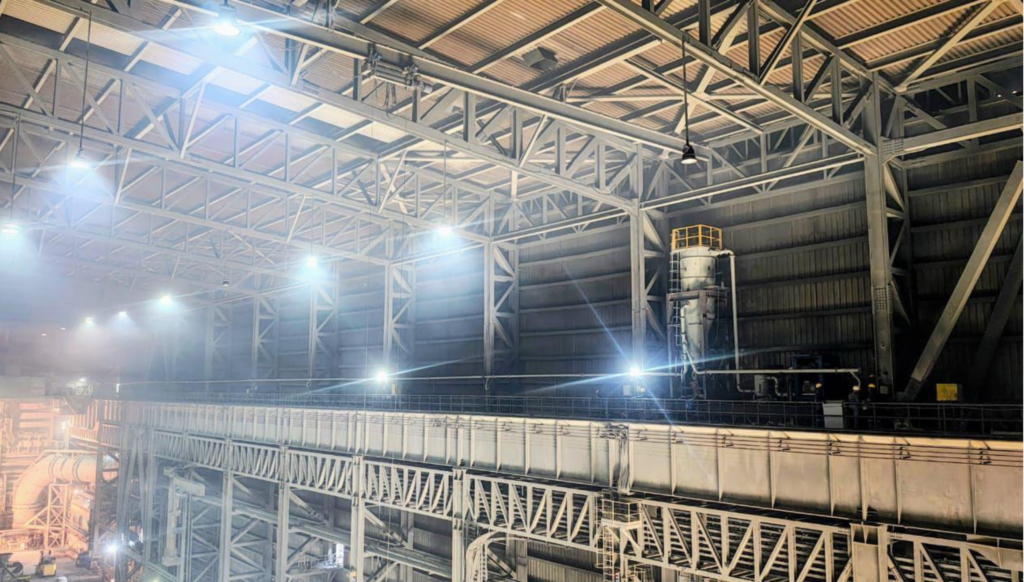
The engineering characteristics of a centralised vacuum system are determined by the plant layout, number and location of suction points, dust type and particle size, required vacuum level, and the conveying distance from the furthest pickup point to the central separator.
01
Negative Pressure Drive
A central vacuum unit — typically a roots blower, side-channel blower, or multistage vacuum pump — creates and maintains suction throughout the fixed piped network. All suction points draw material toward the central collection unit.
02
Fixed Piped Network with Multiple Suction Points
Dedicated vacuum pipeline routes connect to strategically located inlet valves throughout the plant. Operators open an inlet valve and connect a flexible hose — no portable equipment required. Multiple points can be active simultaneously.
03
Central Separation & Collection
All collected dust delivers to a single central filter receiver or cyclone separator, where it is separated from the transport air and discharged to a collection hopper. A downstream bag filter captures fines before clean air is exhausted.
04
Dual Function — Housekeeping & Dust Recovery
A CVCS serves routine housekeeping (cleaning floors, surfaces, and equipment) and fugitive dust recovery (capturing escaped process dust) on one shared network and single central installation.
- System Configurations
Three configurations — tailored to your specific housekeeping and recovery requirements.
SaveEco, in technology partnership with STAG AG Switzerland, designs and supplies centralised vacuum cleaning systems tailored to the specific housekeeping and dust recovery requirements of each industrial application.
Configuration 3.1
Plant Housekeeping Vacuum System
A fixed piped vacuum network serving multiple operator-controlled inlet valve stations across the plant floor, elevated walkways, equipment bases, and structural areas. The central vacuum unit maintains continuous suction; operators open a valve, connect a flexible hose, and clean the area — no portable equipment required.
Drive
Central roots blower or multistage vacuum unit | Suction Points
Multiple fixed inlet valves across plant |
Pipeline
Fixed vacuum pipeline network | Separation
Central cyclone separator or bag filter receiver |
Collection
Central hopper — dust disposal or material recovery | Application
Routine plant housekeeping across large industrial facilities |
Configuration 3.2
Dust Recovery Vacuum System
A dedicated vacuum network connected to fixed pickup hoods, suction nozzles, or suction cups positioned at known dust generation points — conveyor transfer points, bag filter discharge outlets, silo vents, and similar sources. The system operates continuously or on timed cycles without operator intervention.
Operation
Continuous or timed-cycle automatic | Suction Points
Fixed hoods at dust generation sources |
Drive
Central vacuum unit — roots blower or multistage pump | Separation
Cyclone or bag filter receiver |
Collection
Hopper with return to process or disposal | Application
Fugitive dust capture at conveyor transfers, ESP outlets, silo vents |
Configuration 3.3
Integrated Housekeeping + Dust Recovery — Combined System
SaveEco designs combined systems where a single vacuum network and central vacuum unit serves both functions simultaneously: fixed automatic pickup hoods for continuous fugitive dust recovery at process points, and operator-activated inlet valve stations for routine area housekeeping — sharing the same pipeline infrastructure and separator.
The combined system delivers operational flexibility across the plant floor and continuous environmental protection at process emission points — from a single central installation and maintenance point.
- System Design Parameters
Every CVCS is engineered to site-specific conditions.
The three primary parameters that govern system sizing — dust load, particle size, and air volume — must be established during the pre-engineering survey. SaveEco engineers assess each parameter during the site audit before any system is specified.
- 3.1 Dust Load
Dust load is the mass of particulate material that the vacuum system must collect per unit time. It varies significantly across industries and specific plant locations.
| Industry / Location | Typical Dust Load | Basis |
|---|---|---|
| Cement plant — raw mill area | 5 – 30 g/m³ | Clinker and raw meal fugitive dust; varies with plant age and enclosure standard |
| Thermal power plant — ESP gallery | 2 – 15 g/m³ | Fly ash class C/F; finer fraction escaping ESP during maintenance and transfer |
| Steel plant — sinter/cast house | 10 – 50 g/m³ | Metallic fines, flux dust, and refractory particulate in enclosed bays |
| Coal handling — transfer towers | 5 – 40 g/m³ | Coarse and fine coal fines; highly variable with coal type and moisture content |
| Alumina refinery — conveyor gallery | 3 – 20 g/m³ | Calcined alumina, abrasive, fine particle fraction predominates |
| Dust load values are representative ranges based on industrial measurement practice and used for system sizing. Actual values confirmed through site survey. | ||
- 3.2 Particle Size Distribution
Particle size governs suction velocity requirements, pipeline sizing, separator type selection, and filter media specification. Dense phase conveying and vacuum conveying are both sensitive to the particle size distribution of the material being handled.
| Material | Typical d₅₀ | System Design Implication |
|---|---|---|
| Fly Ash (Class F) | 10 – 30 µm | Fine fraction; bag filter mandatory at separator; high filter cloth area required |
| Cement Dust (OPC) | 15 – 45 µm | Abrasive; pipeline material selection critical; cyclone + bag filter combination recommended |
| Limestone Powder | 20 – 75 µm | Moderate abrasion; cyclone pre-separation reduces filter load |
| Coal Dust | 50 – 300 µm | Wider distribution; ATEX provisions required; anti-static pipework and earthing |
| Alumina (Calcined) | 80 – 150 µm | Coarse-to-medium; cyclone efficiency high; abrasion-resistant bends required |
| Zinc Oxide / Metal Oxide | 0.1 – 10 µm | Sub-micron fraction; HEPA-grade final filter; health hazard classification reviewed |
| d₅₀ values are representative of typical industrial bulk powders. Site-specific material testing is recommended for final design. | ||
- 3.3 Air Volume & Vacuum Level
The volumetric air flow required is determined by the number of simultaneously active suction points, the transport velocity needed to convey the specific material, and the total pipeline resistance.
| Design Parameter | Typical Range | Basis |
|---|---|---|
| Transport velocity (in pipe) | 15 – 25 m/s | Sufficient to maintain suspension of fine industrial dust without excessive pipeline erosion |
| Suction nozzle air volume | 150 – 400 m³/hr | Per active suction point; varies with nozzle size (50–100 mm bore) and material type |
| System vacuum level | –150 to –400 mbar | Determined by pipeline length, number of active points, and dust load; roots blower selection based on this envelope |
| Simultaneous active points | 2–6 standard 10+ large installs | Designed at engineering stage based on plant housekeeping requirements and shift patterns |
| Total system air flow | 300 – 4,000 m³/hr | Depends on plant scale; engineered per installation |
| Air-to-cloth ratio (filter) | 1.0 – 2.0 m³/min/m² | Governing parameter for bag filter sizing at the central receiver |
| All ranges are engineering design references consistent with industrial pneumatic vacuum conveying practice. Final specification is derived from site survey and material characterisation. | ||
- Industrial Applications
Installed wherever fugitive dust is a continuous operational and compliance challenge.
Centralised vacuum cleaning systems are installed in heavy industrial facilities where fugitive dust accumulation on plant surfaces and structures is a continuous challenge — operationally and from an environmental and health perspective.
Cement Plants
Clinker handling areas, raw mill buildings, cement dispatch bays, packing plant floors, conveyor transfer towers generating continuous cement dust accumulation on surfaces.
Thermal Power Plants
Coal handling areas, ESP and bag filter gallery floors, turbine hall, coal bunker decks, ash handling buildings — fly ash and coal dust housekeeping.
Integrated Steel Plants
Blast furnace cast houses, converter bays, sinter plant buildings, raw material handling, flux and coal injection areas — fine metallic and process dust.
Alumina Refineries
Alumina powder handling areas, conveyor galleries, silo discharge zones — fine white alumina dust requiring full containment.
Chemical Processing
Fine chemical handling buildings, reactor charging areas, powder packaging lines — sensitive dust requiring zero atmospheric release.
Mineral Processing
Crushing and grinding buildings, concentrate handling, limestone and gypsum storage areas.
- Engineering Advantages
Inherent advantages over manual and mobile housekeeping alternatives.
The following advantages are inherent to the centralised vacuum system approach and apply to correctly designed and installed industrial housekeeping systems.
Eliminates Dust Resuspension
Sweeping and compressed-air blowdown relocate dust — they do not remove it. Centralised vacuum collection removes dust from the plant environment entirely, at the point of pickup, without resuspension.
Improved Occupational Health
Sweeping and compressed-air blowdown relocate dust — they do not remove it. Centralised vacuum collection removes dust from the plant environment entirely, at the point of pickup, without resuspension.
Environmental & Regulatory Compliance
Sweeping and compressed-air blowdown relocate dust — they do not remove it. Centralised vacuum collection removes dust from the plant environment entirely, at the point of pickup, without resuspension.
Reduced Equipment Failures
Sweeping and compressed-air blowdown relocate dust — they do not remove it. Centralised vacuum collection removes dust from the plant environment entirely, at the point of pickup, without resuspension.
Material Recovery — Waste to Value
Sweeping and compressed-air blowdown relocate dust — they do not remove it. Centralised vacuum collection removes dust from the plant environment entirely, at the point of pickup, without resuspension.
Lower Long-Term Operating Cost
Sweeping and compressed-air blowdown relocate dust — they do not remove it. Centralised vacuum collection removes dust from the plant environment entirely, at the point of pickup, without resuspension.
Multi-Point Coverage from One Unit
Sweeping and compressed-air blowdown relocate dust — they do not remove it. Centralised vacuum collection removes dust from the plant environment entirely, at the point of pickup, without resuspension.
- Frequently Asked Question
Common questions about centralised vacuum cleaning systems.
A CVCS is a permanently installed, plant-wide pneumatic vacuum network that collects fugitive dust, dry powder spillage, and industrial particulate from multiple locations across a facility — and transfers everything through sealed pipelines to a single central separator and collection hopper. It replaces manual sweeping, mobile vacuum trolleys, and compressed-air blowdown with a fixed infrastructure served by one central vacuum unit (typically a roots blower or multistage vacuum pump). Operators simply open the nearest inlet valve, connect a flexible hose, and clean — without moving any equipment.
Yes — the majority of installations are brownfield retrofits. Pipework is routed through existing structures using a combination of fixed routes and flexible drops. A plant survey confirms the optimal network layout before design begins.
The central vacuum unit and pipework are sized for the required number of simultaneous users — typically 2–6 in most industrial plant applications. This is confirmed at the design stage based on your cleaning shift pattern and plant size.
The system handles any dry, fine particulate that can be conveyed in a vacuum air stream — cement dust, fly ash, coal dust, limestone powder, alumina, zinc oxide, refractory dust, gypsum, carbon black, and general industrial particulate. Wet, sticky, or highly hygroscopic materials that clump in pipelines are generally not suitable without specific design provisions. Material suitability is confirmed during engineering based on particle size, bulk density, and moisture content.
Manual sweeping and compressed-air blowdown resuspend settled dust into the breathing zone of plant personnel — worsening plant air quality rather than improving it. Centralised vacuum collection captures dust at the point of pickup and removes it entirely within sealed pipelines, with no re-release during transport. This directly reduces airborne dust concentrations in the work environment.
Yes — where collected dust has material value (cement powder, fly ash, alumina), the central collection hopper connects directly to the plant's pneumatic conveying system to return material to storage or process. SaveEco designs combined systems where the vacuum hopper discharges into a lean phase or dense phase conveying vessel, eliminating manual handling of recovered material entirely.
The number depends on central vacuum unit capacity, pipeline network sizing, and the maximum number of simultaneously active suction points. Not all inlet valves need to be open at once — typically only a fraction are in use during routine housekeeping. The system is engineered to the maximum simultaneous usage scenario, which determines vacuum unit and pipeline specification.
A housekeeping system uses operator-activated inlet valve stations — operators open a valve, connect a flexible hose, and clean the area. A dust recovery system uses fixed automatic pickup hoods at known dust generation points that operate continuously or on a timed cycle without operator intervention. SaveEco designs combined systems where both functions share a single pipeline network and vacuum unit.
Maintenance is concentrated at one central location: periodic filter bag cleaning or replacement, routine servicing of the vacuum unit (blower or pump), and emptying of the collection hopper. The fixed vacuum pipeline network requires no routine maintenance — only periodic inspection of joints and supports. This is a significant advantage over distributed mechanical housekeeping equipment.
Special engineering provisions are required for combustible dusts — coal dust, certain metal powders, or some chemical dusts. Measures include anti-static materials, explosion relief venting on the separator, and spark detection where required by dust hazard assessment. SaveEco assesses dust hazard classification and ATEX requirements during the engineering phase and designs accordingly.
Let’s Build a Cleaner Plant Together
Every industrial plant has a unique dust challenge. SaveEco’s engineers assess your specific plant layout, dust type, and housekeeping requirements — and design a Centralised Vacuum Cleaning System that fits your process, not a generic catalogue solution.